IC Package modeling
IC packages form the connection between the IC and a PCB or socket and come in all kind of formats. When they have RF connections often a model is needed to describe the electrical behavior. The objects defining the package space like IC size, number of bondwires, bondwire shape, leadframe, molding plastic and so on define the electrical behavior of the package. All of these variables have an impact and therefore it is practically impossible to define a general package model. For accurate results best practice is to make a 3D model of the IC package and simulate the s-parameters. From these s-parameters a LC package model can be fitted.
The inductance and coupling factors of a bondwire are depended on the return path of the current. This path itself can be depended on the reference of the signal, for example the signal can have a differential or common mode. In bondwire models this return path often is an ideal groundplane, while in packages the IC ground and package ground are coupled via additional bondwires.
Coupled bondwires influence the current distribution in the wire, this has an impact on the Q-factor of the wire. For this reason the Q-factor in common mode can be very different from the Q-factor in differential mode. For the same reason an estimation of the Q-factor based on the losses due to the skin effect can be wrong.
If you do want to estimate the bondwire inductance of a wire above ground you can use the following formula:
L ≈ 0.2*ln(4h/d) [nH/mm], where h is the height and d is the diameter of the wire.
The mutual inductance for two coupled bondwires can be approximated as:
L ≈ 0.1*ln(1+(2h/dx)²) [nH/mm], where h is the height and dx is the spacing
However these formulas should only be used as a rough approximation.
Example of a lead less package (LLP/QFN) model
As an example a part of a LLP package is drawn in the figure below, it contains 7 RF wires to be modeled. The downbonds are used in the return path and therefore partly define the ground (or reference). This ground is certainly not planar. The downbonds could also be modelled individually, however that would cause a significant larger model with large coupling factors. The 7 RF wires are now modelled given the downbonds, so the downbonds are also, but implicitly, modeled.
The 3D model delivers a s-parameter dataset that completely describes the model over the simulated frequency range. To get more insight into the electrical behavior of the wires a LC(R) model is extracted. This model is only valid at a single frequency, but has the advantage that you can understand the influence of the wire characteristics. As such s-parameters are meant for the circuit simulator, the LC(R) model for the RF designer.
 RF part of the LLP, 7 wires + downbonds
|
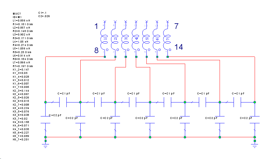 Equivalent LCR model extracted @ 2.44 GHz
|
|---|
The self and mutual inductances are extracted from the s-parameter data. If the LC model is a physically correct model they should be frequency independent, otherwise the LC model is only at the extracted frequency a correct representation. As can be seen in the picture below the self inductances can only be considered constant for low frequencies. Above 4-5 GHz the model looses validity, this effect is largely caused by the physical dimensions of the wires. The wire is not a lumped element but causes a phase delay, this phase delay increases with frequency.
The resistance of the wire is strongly frequency depended, partly due to the skin effect and partly due to the phase delay of the wires which causes an impedance transformation on the real part. If you would draw the resistance in a Smith Chart this becomes evident. Because the wire resistance is hard to model as a frequency independent element the Q of this LCR model will only be valid at the extracted frequency.
 Self inductances are weakly frequency depended
|
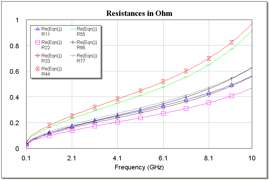 Resistances are strongly frequency depended
|
|---|
As the self inductances and resistances are in general frequency depended and the return path of the current is not a planar ground, simple formulas as given above can only be used in situations where the needed accuracy is low. S-parameters from a 3D model are needed in other cases.
If no s-parameters can be used, for example if the simulations need to be done in the time domain, a lumped model can be used. To increase the validity of these type of models the wire could be modeled as a transmission line instead of an inductor, as this models the delay. The transmission line could be modeled by a so called RLGC model, look at the signal integrity page for an example. This kind of model shows a much better fit at high frequencies.
IC package simulations will give much more realistic results compared to closed formulations as used in bondwire models. If you want help to model your structure send us an email.